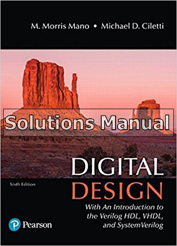
Digital Design With an Introduction to the Verilog HDL VHDL and SystemVerilog 6th Edition Mano Solutions Manual
$26.50$50.00 (-47%)
Digital Design With an Introduction to the Verilog HDL VHDL and SystemVerilog 6th Edition Mano Solutions Manual.
You may also like
Instant download Digital Design With an Introduction to the Verilog HDL VHDL and SystemVerilog 6th Edition Mano Solutions Manual pdf docx epub after payment.
Product details:
- ISBN-10 : 9780134549897
- ISBN-13 : 978-0134549897
- Author:
A modern update to a classic, authoritative text, Digital Design, 5th Edition teaches the fundamental concepts of digital design in a clear, accessible manner. The text presents the basic tools for the design of digital circuits and provides procedures suitable for a variety of digital applications. Like the previous editions, this edition of Digital Design supports a multimodal approach to learning, with a focus on digital design, regardless of language. Recognizing that three public-domain languages―Verilog, VHDL, and SystemVerilog―all play a role in design flows for today’s digital devices, the 5th Edition offers parallel tracks of presentation of multiple languages, but allows concentration on a single, chosen language.
Table of contents:
1 Digital Systems and Binary Numbers
1.1 Digital Systems
1.2 Binary Numbers
1.3 NumberBase Conversions
1.4 Octal and Hexadecimal Numbers
1.5 Complements of Numbers
1.6 Signed Binary Numbers
1.7 Binary Codes
1.8 Binary Storage and Registers
1.9 Binary Logic
2 Boolean Algebra and Logic Gates
2.1 Introduction
2.2 Basic Definitions
2.3 Axiomatic Definition of Boolean Algebra
2.4 Basic Theorems and Properties of Boolean Algebra
2.5 Boolean Functions
2.6 Canonical and Standard Forms
2.7 Other Logic Operations
2.8 Digital Logic Gates
2.9 Integrated Circuits
3 GateLevel Minimization
3.1 Introduction
3.2 The Map Method
3.3 FourVariable K-Map
3.4 ProductofSums Simplification
3.5 Don’tCare Conditions
3.6 NAND and NOR Implementation
3.7 Other TwoLevel Implementations
3.8 ExclusiveOR Function
3.9 Hardware Description Languages (HDLs)
4 Combinational Logic
4.1 Introduction
4.2 Combinational Circuits
4.3 Analysis of Combinational Circuits
4.4 Design Procedure
4.5 Binary Adder—Subtractor
4.6 Decimal Adder
4.7 Binary Multiplier
4.8 Magnitude Comparator
4.9 Decoders
4.10 Encoders
4.11 Multiplexers
4.12 HDL Models of Combinational Circuits
5 Synchronous Sequential Logic
5.1 Introduction
5.2 Sequential Circuits
5.3 Storage Elements: Latches
5.4 Storage Elements: FlipFlops
5.5 Analysis of Clocked Sequential Circuits
5.6 Synthesizable HDL Models of Sequential Circuits
5.7 State Reduction and Assignment
5.8 Design Procedure
6 Registers and Counters
6.1 Registers
6.2 Shift Registers
6.3 Ripple Counters
6.4 Synchronous Counters
6.5 Other Counters
6.6 HDL Models of Registers and Counters
7 Memory and Programmable Logic
7.1 Introduction
7.2 RandomAccess Memory
7.3 Memory Decoding
7.4 Error Detection and Correction
7.5 ReadOnly Memory
7.6 Programmable Logic Array
7.7 Programmable Array Logic
7.8 Sequential Programmable Devices
8 Design at the Register Transfer Level
8.1 Introduction
8.2 Register Transfer Level (RTL) Notation
8.3 RTL descriptions VERILOG (Edge- and Level-Sensitive Behaviors)
8.4 Algorithmic State Machines (ASMs)
8.5 Design Example (ASMD Chart)
8.6 HDL Description of Design Example
8.7 Sequential Binary Multiplier
8.8 Control Logic
8.9 HDL Description of Binary Multiplier
8.10 Design with Multiplexers
8.11 RaceFree Design (Software Race Conditions)
8.12 LatchFree Design (Why Waste Silicon?)
8.13 System Verilog–An Introduction
9 Laboratory Experiments with Standard ICs and FPGAs
9.1 Introduction to Experiments
9.2 Experiment 1: Binary and Decimal Numbers
9.3 Experiment 2: Digital Logic Gates
9.4 Experiment 3: Simplification of Boolean Functions
9.5 Experiment 4: Combinational Circuits
9.6 Experiment 5: Code Converters
9.7 Experiment 6: Design with Multiplexers
9.8 Experiment 7: Adders and Subtractors
9.9 Experiment 8: FlipFlops
9.10 Experiment 9: Sequential Circuits
9.11 Experiment 10: Counters
9.12 Experiment 11: Shift Registers
9.13 Experiment 12: Serial Addition
9.14 Experiment 13: Memory Unit
9.15 Experiment 14: Lamp Handball
9.16 Experiment 15: ClockPulse Generator
9.17 Experiment 16: Parallel Adder and Accumulator
9.18 Experiment 17: Binary Multiplier
9.19 HDL Simulation Experiments and Rapid Prototyping with FPGAs
10 Standard Graphic Symbols
10.1 RectangularShape Symbols
10.2 Qualifying Symbols
10.3 Dependency Notation
10.4 Symbols for Combinational Elements
10.5 Symbols for FlipFlops
10.6 Symbols for Registers
10.7 Symbols for Counters
10.8 Symbol for RAM
Appendix
Answers to Selected Problems
Index


