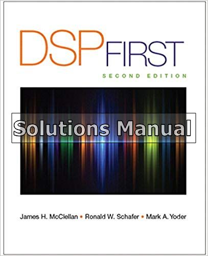
DSP First 2nd Edition McClellan Solutions Manual
You may also like
Instant download DSP First 2nd Edition McClellan Solutions Manual pdf docx epub after payment.
Product Details:
- ISBN-10 : 0136019250
- ISBN-13 : 978-0136019251
- Author:
DSP First and it’s accompanying digital assets are the result of more than 20 years of work that originated from, and was guided by, the premise that signal processing is the best starting point for the study of electrical and computer engineering. The “DSP First” approach introduces the use of mathematics as the language for thinking about engineering problems, lays the groundwork for subsequent courses, and gives students hands-on experiences with MATLAB.
The Second Edition features three new chapters on the Fourier Series, Discrete-Time Fourier Transform, and the The Discrete Fourier Transform as well as updated labs, visual demos, an update to the existing chapters, and hundreds of new homework problems and solutions.
Table of contents:
1-1 Mathematical Representation of Signals
1-2 Mathematical Representation of Systems
1-3 Systems as Building Blocks
1-4 The Next Step
Sinusoids
2-1 Tuning Fork Experiment
2-2 Review of Sine and Cosine Functions
2-3Sinusoidal Signals
2-3.1Relation of Frequency to Period
2-3.2 Phase and Time Shift
2-4 Sampling and Plotting Sinusoids
2-5Complex Exponentials and Phasors
2-5.1 Review of Complex Numbers
2-5.2 Complex Exponential Signals
2-5.3 The Rotating Phasor Interpretation
2-5.4 Inverse Euler Formulas Phasor Addition
2-6Phasor Addition
2-6.1 Addition of Complex Numbers
2-6.2 Phasor Addition Rule
2-6.3 Phasor Addition Rule: Example
2-6.4 MATLAB Demo of Phasors
2-6.5 Summary of the Phasor Addition Rule Physics of the Tuning Fork
2-7.1 Equations from Laws of Physics
2-7.2 General Solution to the Differential Equation
2-7.3 Listening to Tones
2-8Time Signals: More Than Formulas
Summary and Links
Problems
Spectrum Representation
3-1 The Spectrum of a Sum of Sinusoids
3-1.1 Notation Change
3-1.2 Graphical Plot of the Spectrum
3-1.3 Analysis vs. Synthesis
Sinusoidal Amplitude Modulation
3-2.1 Multiplication of Sinusoids
3-2.2 Beat Note Waveform
3-2.3 Amplitude Modulation
3-2.4 AM Spectrum
3-2.5 The Concept of Bandwidth
Operations on the Spectrum
3-3.1 Scaling or Adding a Constant
3-3.2 Adding Signals
3-3.3 Time-Shifting x.t/ Multiplies ak by a Complex Exponential
3-3.4 Differentiating x.t/ Multiplies ak by .j 2nfk/
3-3.5 Frequency Shifting
Periodic Waveforms
3-4.1 Synthetic Vowel
3-4.3 Example of a Non-periodic Signal
Fourier Series
3-5.1 Fourier Series: Analysis
3-5.2 Analysis of a Full-Wave Rectified Sine Wave
3-5.3 Spectrum of the FWRS Fourier Series
3-5.3.1 DC Value of Fourier Series
3-5.3.2 Finite Synthesis of a Full-Wave Rectified Sine
Time—Frequency Spectrum
3-6.1 Stepped Frequency
3-6.2 Spectrogram Analysis
Frequency Modulation: Chirp Signals
3-7.1 Chirp or Linearly Swept Frequency
3-7.2 A Closer Look at Instantaneous Frequency
Summary and Links
Problems
Fourier Series
Fourier Series Derivation
4-1.1 Fourier Integral Derivation
Examples of Fourier Analysis
4-2.1 The Pulse Wave
4-2.1.1 Spectrum of a Pulse Wave
4-2.1.2 Finite Synthesis of a Pulse Wave
4-2.2 Triangle Wave
4-2.2.1 Spectrum of a Triangle Wave
4-2.2.2 Finite Synthesis of a Triangle Wave
4-2.3 Half-Wave Rectified Sine
4-2.3.1 Finite Synthesis of a Half-Wave Rectified Sine
Operations on Fourier Series
4-3.1 Scaling or Adding a Constant
4-3.2 Adding Signals
4-3.3 Time-Scaling
4-3.4 Time-Shifting x.t/ Multiplies ak by a Complex Exponential
4-3.5 Differentiating x.t/ Multiplies ak by .j!0k/
4-3.6 Multiply x.t/ by Sinusoid
Average Power, Convergence, and Optimality
4-4.1 Derivation of Parseval’s Theorem
4-4.2 Convergence of Fourier Synthesis
4-4.3 Minimum Mean-Square Approximation
Pulsed-Doppler Radar Waveform
4-5.1 Measuring Range and Velocity
Problems
Sampling and Aliasing
Sampling
5-1.1 Sampling Sinusoidal Signals
5-1.2 The Concept of Aliasing
5-1.3 Spectrum of a Discrete-Time Signal
5-1.4 The Sampling Theorem
5-1.5 Ideal Reconstruction
Spectrum View of Sampling and Reconstruction
5-2.1 Spectrum of a Discrete-Time Signal Obtained by Sampling
5-2.2 Over-Sampling
5-2.3 Aliasing Due to Under-Sampling
5-2.4 Folding Due to Under-Sampling
5-2.5 Maximum Reconstructed Frequency
Strobe Demonstration
5-3.1 Spectrum Interpretation
Discrete-to-Continuous Conversion
5-4.1 Interpolation with Pulses
5-4.2 Zero-Order Hold Interpolation
5-4.3 Linear Interpolation
5-4.4 Cubic Spline Interpolation
5-4.5 Over-Sampling Aids Interpolation
5-4.6 Ideal Bandlimited Interpolation
The Sampling Theorem
Summary and Links
Problems
FIR Filters
6-1 Discrete-Time Systems
6-2 The Running-Average Filter
6-3 The General FIR Filter
6-3.1 An Illustration of FIR Filtering
The Unit Impulse Response and Convolution
6-4.1 Unit Impulse Sequence
6-4.2 Unit Impulse Response Sequence
6-4.2.1 The Unit-Delay System
6-4.3 FIR Filters and Convolution
6-4.3.1 Computing the Output of a Convolution
6-4.3.2 The Length of a Convolution
6-4.3.3 Convolution in MATLAB
6-4.3.4 Polynomial Multiplication in MATLAB
6-4.3.5 Filtering the Unit-Step Signal
6-4.3.6 Convolution is Commutative
6-4.3.7 MATLAB GUI for Convolution
Implementation of FIR Filters
6-5.1 Building Blocks
6-5.1.1 Multiplier
6-5.1.2 Adder
6-5.1.3 Unit Delay
6-5.2 Block Diagrams
6-5.2.1 Other Block Diagrams
6-5.2.2 Internal Hardware Details
Linear Time-Invariant (LTI) Systems
6-6.1 Time Invariance
6-6.2 Linearity
6-6.3 The FIR Case
Convolution and LTI Systems
6-7.1 Derivation of the Convolution Sum
6-7.2 Some Properties of LTI Systems
Cascaded LTI Systems
Example of FIR Filtering
Summary and Links
Problems Frequency Response of FIR Filters
7-1 Sinusoidal Response of FIR Systems
7-2 Superposition and the Frequency Response
7-3 Steady-State and Transient Response
7-4 Properties of the Frequency Response
7-4.1 Relation to Impulse Response and Difference Equation
7-4.2 Periodicity of H.ej !O /
7-4.3 Conjugate Symmetry Graphical Representation of the Frequency Response
7-5.1 Delay System
7-5.2 First-Difference System
7-5.3 A Simple Lowpass Filter Cascaded LTI Systems
Running-Sum Filtering
7-7.1 Plotting the Frequency Response
7-7.2 Cascade of Magnitude and Phase
7-7.3 Frequency Response of Running Averager
7-7.4 Experiment: Smoothing an Image
Filtering Sampled Continuous-Time Signals
7-8.1 Example: Lowpass Averager
7-8.2 Interpretation of Delay
Summary and Links
Problems
The Discrete-Time Fourier Transform
DTFT: Discrete-Time Fourier Transform
8-1.1 The Discrete-Time Fourier Transform
8-1.1.1 DTFT of a Shifted Impulse Sequence
8-1.1.2 Linearity of the DTFT
8-1.1.3 Uniqueness of the DTFT
8-1.1.4 DTFT of a Pulse
8-1.1.5 DTFT of a Right-Sided Exponential Sequence
8-1.1.6 Existence of the DTFT
8-1.2 The Inverse DTFT
8-1.2.1 Bandlimited DTFT
8-1.2.2 Inverse DTFT for the Right-Sided Exponential
8-1.3 The DTFT is the Spectrum
Properties of the DTFT
8-2.1 The Linearity Property
8-2.2 The Time-Delay Property
8-2.3 The Frequency-Shift Property
8-2.3.1 DTFT of a Complex Exponential
8-2.3.2 DTFT of a Real Cosine Signal
8-2.4 Convolution and the DTFT
8-2.4.1 Filtering is Convolution
8-2.5 Energy Spectrum and the Autocorrelation Function
8-2.5.1 Autocorrelation Function
Ideal Filters
8-3.1 Ideal Lowpass Filter
8-3.2 Ideal Highpass Filter
8-3.3 Ideal Bandpass Filter
Practical FIR Filters
8-4.1 Windowing
8-4.2 Filter Design
8-4.2.1 Window the Ideal Impulse Response
8-4.2.2 Frequency Response of Practical Filters
8-4.2.3 Passband Defined for the Frequency Response
8-4.2.4 Stopband Defined for the Frequency Response
8-4.2.5 Transition Zone of the LPF
8-4.2.6 Summary of Filter Specifications
8-4.3 GUI for Filter Design
Table of Fourier Transform Properties and Pairs
Summary and Links
Problems
The Discrete Fourier Transform
Discrete Fourier Transform (DFT)
9-1.1 The Inverse DFT
9-1.2 DFT Pairs from the DTFT
9-1.2.1 DFT of Shifted Impulse
9-1.2.2 DFT of Complex Exponential
9-1.3 Computing the DFT
9-1.4 Matrix Form of the DFT and IDFT
Properties of the DFT
9-2.1 DFT Periodicity for XŒk]
9-2.2 Negative Frequencies and the DFT
9-2.3 Conjugate Symmetry of the DFT
9-2.3.1 Ambiguity at XŒN=2]
9-2.4 Frequency Domain Sampling and Interpolation
9-2.5 DFT of a Real Cosine Signal
Inherent Periodicity of xŒn] in the DFT
9-3.1 DFT Periodicity for xŒn]
9-3.2 The Time Delay Property for the DFT
9-3.2.1 Zero Padding
9-3.3 The Convolution Property for the DFT
Table of Discrete Fourier Transform Properties and Pairs
Spectrum Analysis of Discrete Periodic Signals
9-5.1 Periodic Discrete-time Signal: Fourier Series
9-5.2 Sampling Bandlimited Periodic Signals
9-5.3 Spectrum Analysis of Periodic Signals
Windows
9-6.0.1 DTFT of Windows
The Spectrogram
9-7.1 An Illustrative Example
9-7.2 Time-Dependent DFT
9-7.3 The Spectrogram Display
9-7.4 Interpretation of the Spectrogram
9-7.4.1 Frequency Resolution
9-7.5 Spectrograms in MATLAB
The Fast Fourier Transform (FFT)
9-8.1 Derivation of the FFT
9-8.1.1 FFT Operation Count
Summary and Links
Problems
z-Transforms
Definition of the z-Transform
Basic z-Transform Properties
10-2.1 Linearity Property of the z-Transform
10-2.2 Time-Delay Property of the z-Transform
10-2.3 A General z-Transform Formula
The z-Transform and Linear Systems
10-3.1 Unit-Delay System
10-3.2 z-1 Notation in Block Diagrams
10-3.3 The z-Transform of an FIR Filter
10-3.4 z-Transform of the Impulse Response
10-3.5 Roots of a z-transform Polynomial
Convolution and the z-Transform
10-4.1 Cascading Systems
10-4.2 Factoring z-Polynomials
10-4.3 Deconvolution
Relationship Between the z-Domain and the !O -Domain
10-5.1 The z-Plane and the Unit Circle
The Zeros and Poles of H.z/
10-6.1 Pole-Zero Plot
10-6.2 Significance of the Zeros of H.z/
10-6.3 Nulling Filters
10-6.4 Graphical Relation Between z and !O
10-6.5 Three-Domain Movies
Simple Filters
10-7.1 Generalize the L-Point Running-Sum Filter
10-7.2 A Complex Bandpass Filter
10-7.3 A Bandpass Filter with Real Coefficients
Practical Bandpass Filter Design
Properties of Linear-Phase Filters
10-9.1 The Linear-Phase Condition
10-9.2 Locations of the Zeros of FIR Linear-Phase Systems
Summary and Links
Problems
IIR Filters
The General IIR Difference Equation
Time-Domain Response
11-2.1 Linearity and Time Invariance of IIR Filters
11-2.2 Impulse Response of a First-Order IIR System
11-2.3 Response to Finite-Length Inputs
11-2.4 Step Response of a First-Order Recursive System
System Function of an IIR Filter
11-3.1 The General First-Order Case
11-3.2 H.z/ from the Impulse Response
11-3.3 The z-Transform Method
The System Function and Block-Diagram Structures
11-4.1 Direct Form I Structure
11-4.2 Direct Form II Structure
11-4.3 The Transposed Form Structure
Poles and Zeros
11-5.1 Roots in MATLAB
11-5.2 Poles or Zeros at z D 0 or 1
11-5.3 Output Response from Pole Location
Stability of IIR Systems
11-6.1 The Region of Convergence and Stability
Frequency Response of an IIR Filter
11-7.1 Frequency Response using MATLAB
11-7.2 Three-Dimensional Plot of a System Function
Three Domains
The Inverse z-Transform and Some Applications
11-9.1 Revisiting the Step Response of a First-Order System
11-9.2 A General Procedure for Inverse z-Transformation
Steady-State Response and Stability
Second-Order Filters
11-11.1 z-Transform of Second-Order Filters
11-11.2 Structures for Second-Order IIR Systems
11-11.3 Poles and Zeros
11-11.4 Impulse Response of a Second-Order IIR System
11-11.4.1 Distinct Real Poles
11-11.5 Complex Poles
Frequency Response of Second-Order IIR Filter
11-12.1 Frequency Response via MATLAB
11-12.23-dB Bandwidth
11-12.3 Three-Dimensional Plot of System Functions
Example of an IIR Lowpass Filter
Summary and Links
Problems
People also search:
DSP First 2nd Edition
DSP First 2nd Edition pdf
DSP First 2nd Edition
dsp first a multimedia approach pdf
dsp the first academy
|
dsp first movie as music director
|

